คู่มือการใช้งาน เครื่องบันทึกภาพ DVR AHD 73500
Last updated: 10 มิ.ย. 2563 | 7990 จำนวนผู้เข้าชม |

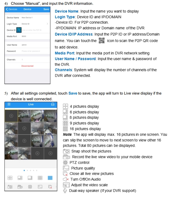
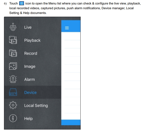
![]()
SAFETY INSTRUCTION
Please carefully read the following safety instruction so as to avoid personal injuries and prevent
the equipment and other connection devices from being damaged.
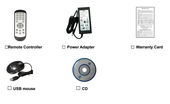
1. Power sources (note: please use the power supply attached or specified by the manufacturer) Never operate the equipment by using unspecified power supply.
2. Never push objects of any kind through openings of DVR Never push objects of any kind through openings of DVR so as to avoid electric shock or other accidents.
3. Do not put the equipment in the dusty field Do not put the equipment in the dusty field.
4. Do not place the equipment under rain or humid environment Do not place the equipment under humid environment like basement. If the equipment is accidentally in contact with water, please unplug the power cable and immediately contact your local dealer.
5. Keep the surface of the equipment clean and dry Use soft damp cloth to clean the outer case of DVR (do not use liquid aerosol cleaners)
6. Do not operate if any problems are found If there are any strange smell or sound from DVR, unplug the power cable and contact the authorized dealer or service center.
7. Do not try to remove the upper cover Warning: Do not remove the cap of DVR so as to avoid electric shock.
8. Handle with care If DVR does not work normally because of hitting on the hard object, please contact the authorized dealer for repair or replacement.
9. Use standard lithium battery (Note: Use the batteries attached or specified by the manufacturer) After cutting off the power supply, if the system clock cannot continue to work, please replace the standard 3V lithium battery on the main board. Warning: Turn off DVR before replacing the batteries, or you may be suffered from serious electric shock. Please properly dispose of the used batteries.
10. Put the equipment in a place with good ventilation The DVR system includes HDD, which produces large amount of heat during operation. As a result, do not block the ventilation openings (on the top, bottom, both sides and the reverse side) for cooling the system during operation. Install or put the equipment in the place with good ventilation.
11. The attached power adapter can only be used for 1 set of DVR. Do not connect more equipment, or DVR may be restarted repeatedly because of insufficient power.
12. Prevent the equipment from water dropping or splashing. Do not place objects containing water, such as flower vase, on the equipment.
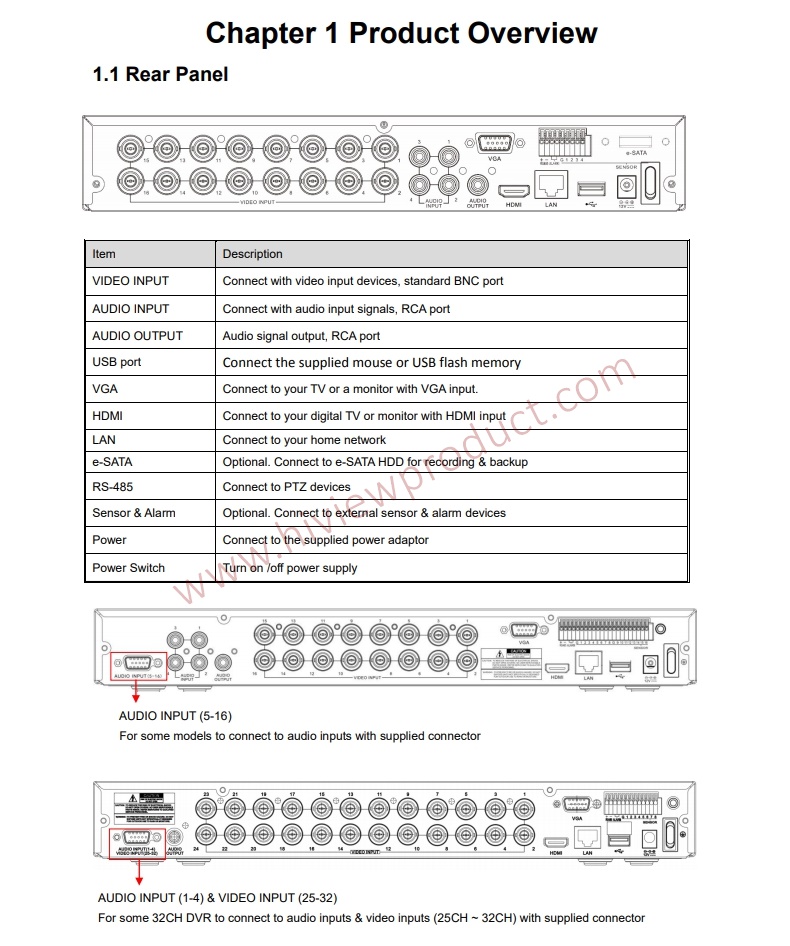
Chapter 2 DVR Installation & Connection
2.1 HDD Installation
Depending on the package you have purchased, the hard disk drive may be included in the full package. If it is not pre-installed, follow the installation instructions on this user manual.
Caution: DO NOT install or remove the hard disk drive while the device power is turned ON.
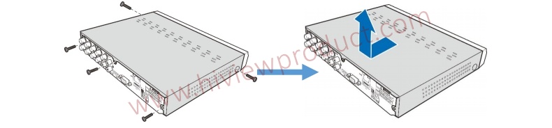
HDD Installation:
(1) Cut power firstly, and then remove screws on both sides & rear panel, and open DVR upper cover.
(2) Connect the data and power cables to the HDD and place the HDD on the DVR case. Carefully flip the DVR case and secure the HDD to the DVR with the screws.
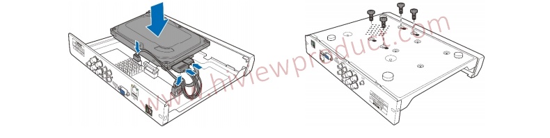
(3) Put the upper cover back carefully, and fix the cover with screws.
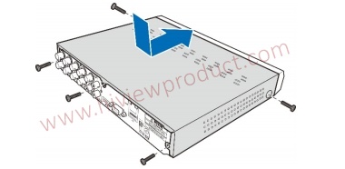
Note: Above procedures are for reference only. The practical operation may be different
depending on the DVR you purchased.
2.2 Connection Diagram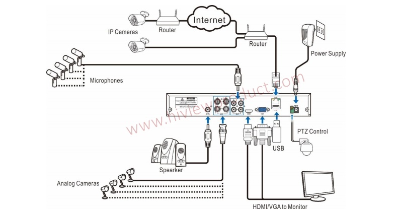
Note: Above diagram is for reference only. The practical connection may be different depending
on the DVR you purchased
2.3 Power Supply Connection
Caution: Use only the supplied power adapter that came with the DVR

Chapter 3 DVR Common Operations
3.1 Using the Supplied Mouse
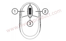 1. Left Button:
o Click to select menu options.
o During live viewing in split-screen view, double-click on a channel to view it in full-screen.
Double-click the channel again to return to split-screen viewing.
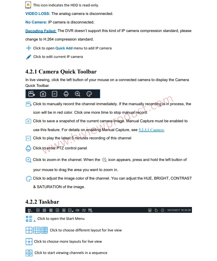
o Click upon a channel on Live Viewing screen to open Camera Quick Toolbar.
o Click and hold to drag sliders and scales on menu mode
2. Right Button:
o Click once to open the Taskbar on the Live Viewing screen. View Taskbar on 4.2.2 Taskbar
o In menus, click to go back / close menus.
3. Scroll Wheel:
o In menus, scroll to move up / down through the menu content.
o While hovering over the volume control wheel, scroll to turn system volume up / down.
3.2 Using the Virtual Keyboard
You will see the virtual keyboard automatically on the screen when you need to enter data
Click to toggle the keyboard to
upper case and more punctuation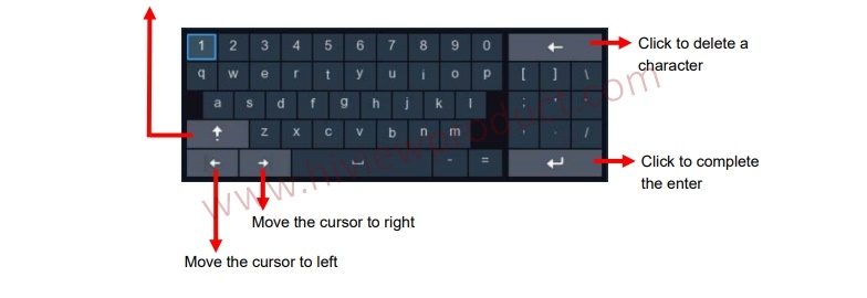
3.3 Password
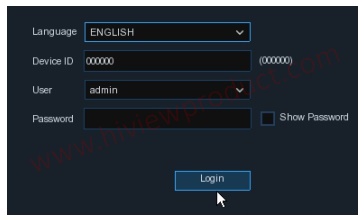
For the first time when you run the DVR, you must be required to set your own password immediately in order to protect your privacy. Please be sure to record your username and password and save them in a secure place. 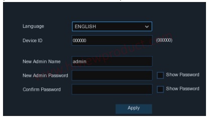
Language: Choose an OSD language
Device ID: Input the device ID in the parentheses. Default ID is 000000. View more about Device
ID on 5.6.1 General.
New Admin name: To set your own administrator name.
New Admin Password: To set your own password. The password must be a combination of 8
characters.
Corfirm Password: Enter your own password again.
Click Apply to confirm your settings and goes to the login interface. Enter your user name &
password to Login the DVR system.

NOTE: If you forget your password, you will be unable to login the system, please contact your reseller to reset the password.
Chapter 4 DVR Starting up
4.1 Start Wizard
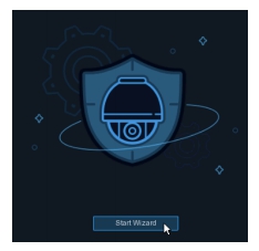
Startup Wizard will help to configure the system and get the DVR works quickly.
4.1.1 Start Wizard
Click the Start Wizard to proceed to the next step
4.1.2 Network Configuration
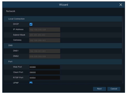
If you connect to a router allows to use DHCP, please check the DHCP box. The router will assignautomatically all the network parameters for your DVR. Unless the network is manually addressedbelow parameters:
IP Address: The IP address identifies the DVR in the network. It consists of four groups of
numbers between 0 to 255, separated by periods. For example, “192.168.001.100”.
Subnet Mask: Subnet mask is a network parameter which defines a range of IP addresses that can be used in a network. If IP address is like a street where you live then subnet mask is like a neighborhood. The subnet address also consists of four groups of numbers, separated by periods. For example, “255.255.000.000”.
Gateway: This address allows the DVR to access the Internet. The format of the Gateway address is the same as the IP Address. For example, “192.168.001.001”.
DNS1/DNS2: DNS1 is the primary DNS server and DNS2 is a backup DNS server. Usually shouldbe enough just to enter the DNS1 server address.
Port
Web Port: This is the port that you will use to log in remotely to the DVR (e.g. using the Web
Client). If the default port 80 is already taken by other applications, please change it. Client Port: This is the port that the DVR will use to send information through (e.g. using the mobile app). If the default port 9000 is already taken by other applications, please change it.
RTSP Port: This is the port that the DVR will be allowed to transmit real-time streaming to other device (e.g. using a streaming Media player.).
UPNP: If you want to log in remotely to the DVR using Web Client, you need to complete the port forwarding in your router. Enable this option if your router supports the UPnP. In this case, you do not need to configure manually port forwarding on your router. If your router does not support UPnP, make sure the port forwarding is completed manually in your router.
PPPoE
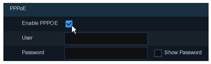
This is an advanced protocol that allows the DVR to connect to the network more directly via DSL
modem.
Check the “Enable PPPOE” box, and then enter the User name & Password of the PPPoE.
3G
This is a prior using the mobile network, you need to connect a 3G dongle to the DVR.
Enable the 3G option, enter the APN, Dial Code, User name & password according to the
instruction of your 3G dongle device.
4.1.3 Date/Time
This menu allows you to configure the Date, Time, Date Format, Time Format, Time Zone, NTP
and DST.
Date and Time
Click on the calendar icon to set the current system date.
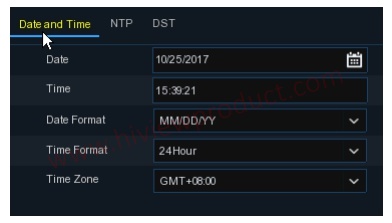
Date: Click on the calendar icon to set the system date.
Time: Click to set the system time.
Date Format: Choose from the dropdown menu to set preferred date format.
Time Format: Choose time format between 24Hour and 12Hour.
Time Zone: Set the correct time zone.
NTP
NTP stands for Network Time Protocol. This feature allows you to synchronize the date and time
automatically on the DVR over Internet. Therefore, the DVR needs to be connected to the Internet.

Check the “NTP” box, and select the NTP server.
DST
DST stands for Daylight Savings Time.
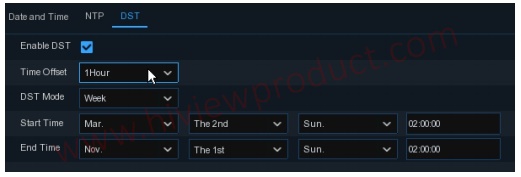
DST: Enable if Daylight Saving Time (DST) is observed in your region
Time Offset: Select the amount of time to offset for DST
Time Mode: Choose to set the daylight saving time in weeks or in days
Start Time/End Time: Set the start time and end time for daylight saving
4.1.4 IP Camera
This menu allows you to add IP cameras to the DVR.
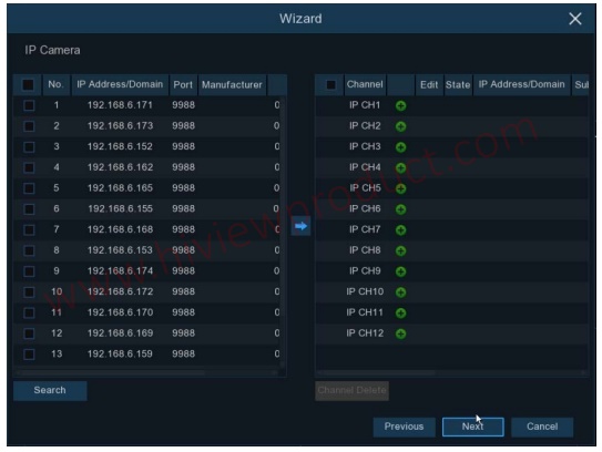
Click Search to search IP cameras in the same network. Choose the IP camera(s) you want to add, and then click icon to add to the DVR.
Enter the camera’s user name & password to add the camera(s).
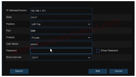
You can also click button to add individual IP camera to a single channel.
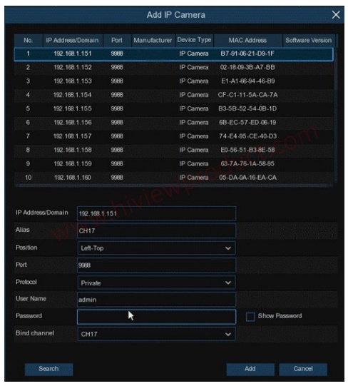
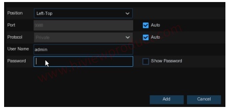
Click Search button to search IP cameras, and then click one of the IP camera in the device list.
IP Address/Domain: IP address or domain name of the IP camera
Alias: Name of the IP camera
Position: Position to display the camera name on the screen.
Port: Port of the IP camera
Protocol: Choose the protocol of the IP camera from the dropdown menu
User Name: User Name of the IP camera
Password: Password of the IP camera
Bind channel: Choose a channel of the DVR you want to attach to
4.1.5 Disk
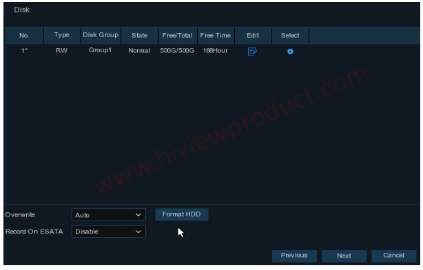
If the HDD is installed in the DVR for the first time, it must be formatted. Select the HDD and then
click Format HDD button to format the HDD.
Overwrite: Use this option to overwrite the old recordings on the HDD when the HDD is full. For
example, if you choose the option 7 days then only the last 7 days recordings are kept on the HDD.
To prevent overwriting any old recordings, select Disable. If you have disabled this function, please
check the HDD status regularly, to make sure the HDD is not full.
Record On ESATA: If your DVR comes with an e-SATA port on the rear panel, you can enable to
record the video to e-SATA HDD.
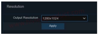
4.1.6 Resolution
Choose an output resolution matches to your monitor. The DVR supports to adjust the output resolution automatically to match the best resolution of your monitor when the system is starting
up.
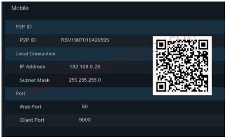
4.1.7 Mobile
If your DVR come with a P2P ID, you can scan the QR code with your mobile app to view the DVR remotely.
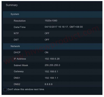
4.1.8 Summary
You can check the system summary information you had set in the start wizard and finish the wizard.
Tick “Don't show this window next time" if you don’t want to display Start Wizard when system
reboot next time. Click Finish button to save & exit.
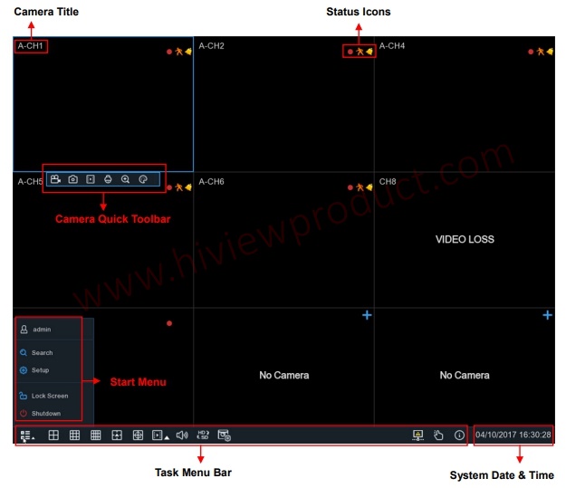
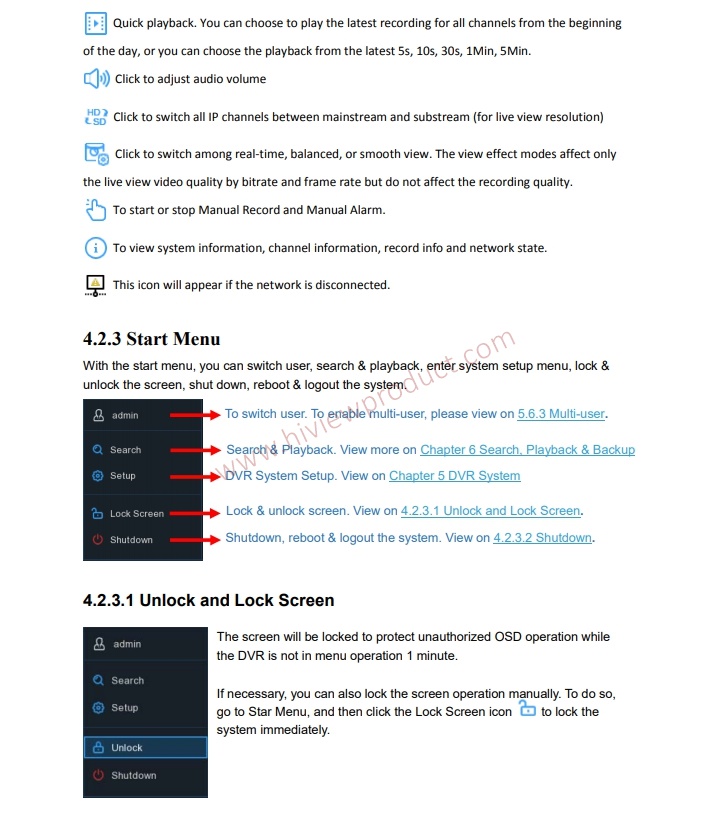
4.2 Live View Screen Overview
4.2.3.2 Shutdown
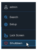
Click the Shutdown button from Star Menu, and the check the further action you want to move.
Click OK button, system will require to input the Admin password to authenticate.
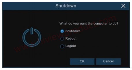
If you choose Logout the system, the live viewing screen will be disappeared. You will need to login the system for further operations.
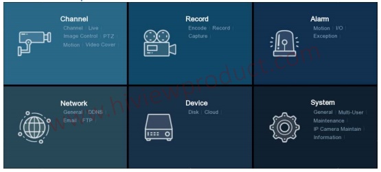
Chapter 5 DVR System Setup
You are able to configure the DVR for Channel, Record, Alarm, Network, Device & System from
Start Menu Setup.
5.1 Channel
In this section, you are allowed to configure the camera, live view display, manage IP cameras, adjust IP camera’s image, PTZ setup, motion setup, convert mode, and more.
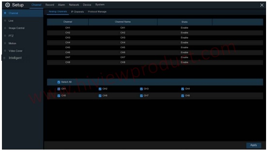
5.1.1 Channel
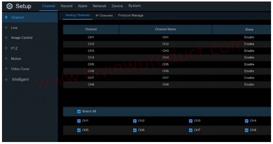
5.1.1.1 Analog Channels
The DVR supports to disable analog channels to increase IP channels. If you want to disable an analog channel, uncheck the box and click Apply to save. To disable an analog channel can increase an IP channel input. To do so, you need to enable the XVR mode in advance at System General Mode, view more on 5.6.1 General.
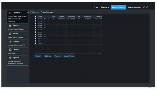
5.1.1.2 IP Channels
If you enable the XVR mode for the DVR, it supports to add IP cameras & modify IP channels.
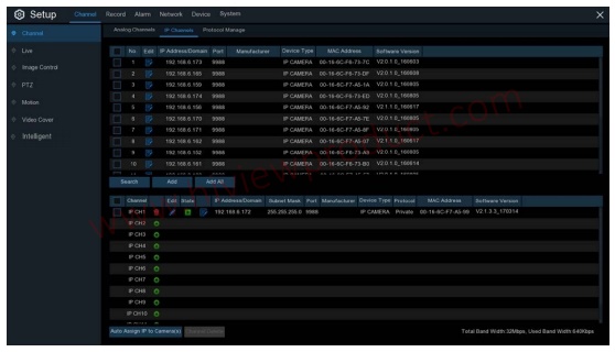
Click Search to search IP cameras from local network, click Add to add individual IP camera, click Add All to add all IP cameras.
Click Search button to search IP cameras, and then click one of the IP camera in the device list.
IP Address/Domain: IP address or domain name of the IP camera
Alias: Name of the IP camera
Position: Position to display the camera name on the screen.
Port: Port of the IP camera
Protocol: Choose the protocol of the IP camera from the dropdown menu
User Name: User Name of the IP camera
Password: Password of the IP camera
Bind channel: Choose a channel of the DVR you want to attach to
Auto Assign IP to Camera(s): The added IP camera would be not able to connect if its IP
address is not in the same network segment with DVR. With this function to reassign an IP
address to all added IP cameras.
Channel Delete: Choose one or more added IP cameras, and click this button to detele.
5.1.1.3 Protocol Manage
With the Protocol Manage, you can edit your own RTSP protocol for IP camera connection
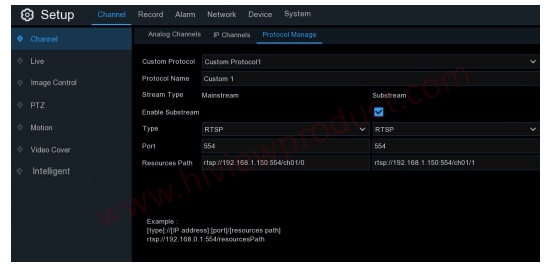
Custom Protocol: The system support max. 10 custom protocol options.
Protocol Name: To give a name to your custom protocol.
Enable Substrearm: Check the box if you want to enable sub-stream.
Type: Only RTSP available now.
Port: Input the RTSP port of your IP camera.
Resources Path: Input the RTSP address of your IP camera.
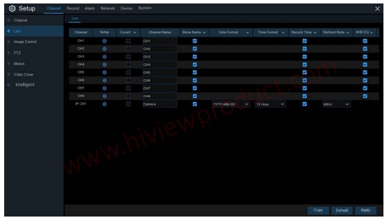
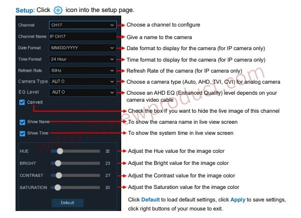
5.1.2 Live
To configure camera parameters.
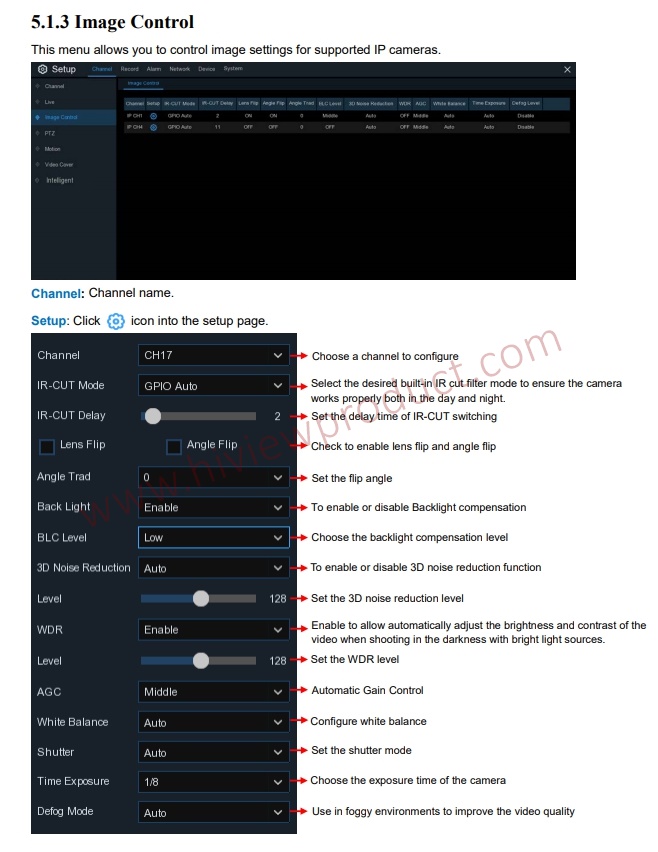
5.1.3 Image Control
This menu allows you to control image settings for supported IP cameras
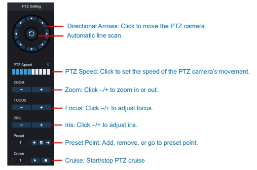
5.1.4 PTZ
This menu allows you to configure the PTZ (Pan-Tilt-Zoom) settings for the dome camera
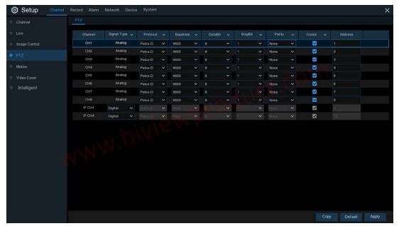
Channel: Channel name
Signal Type: Analog for analog channels, Analog & Digital for IP channels. Protocol: Choose the communication protocol between the PTZ capable camera and DVR. If your camera support UTC (Up the Coax) function, you can choose COAX1 or COAX2 to display your camera OSD menu or control the UTC PTZ function.
Baudrate: The speed of the information sent from the DVR to the PTZ-capable camera. Make sure it matches the compatibility level of your PTZ-capable camera.
DataBit / StopBit: The information between the DVR and PTZ-capable camera is sent in individual packages. The DataBit indicates the number of bits sent, while the EndBit indicates the end of the package and the beginning of the next (information) package. The available parameters for DataBit are: 8, 7, 6, 5. the available parameters for the StopBit are 1 or 2.
Parity: For error check. See the documentation of your PTZ-capable camera, to configure this setting.
Cruise: Enable to use the Cruise mode. In order to use the Cruise mode, you need to set a number of preset points.
Address: Set the command address of the PTZ system. Please be noted that each PTZ-capable
camera needs a unique address to function properly
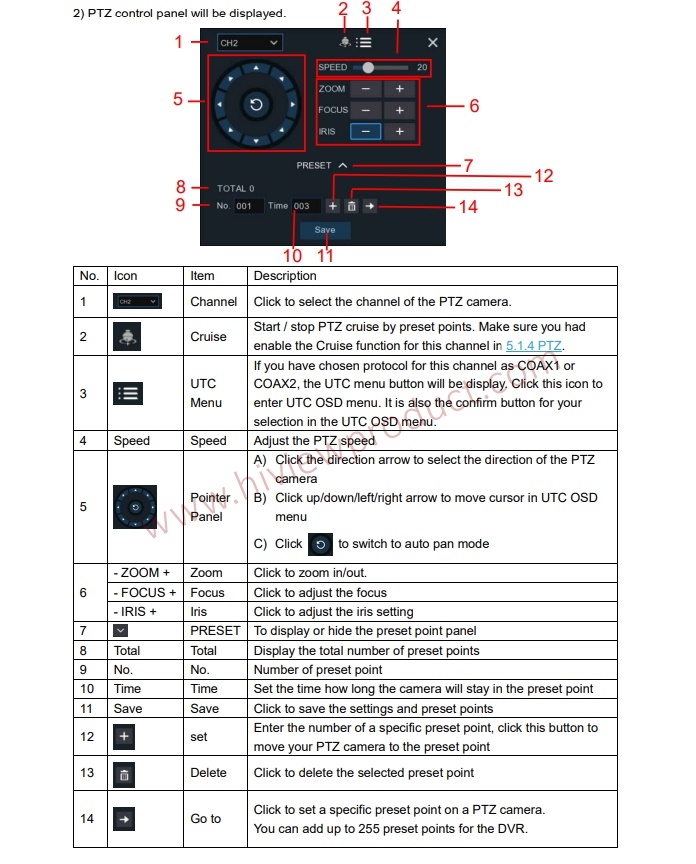
5.1.4.1 PTZ control
After finishing the PTZ setup, you can use the PTZ function to control your PTZ camera.
1) Click left your mouse upon a channel on Live Viewing screen to open Camera Quick Toolbar,
and choose the PTZ control icon .
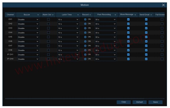
5.1.5 Motion
This menu allows you to configure motion parameters. When motion has been detected by one or more cameras, your DVR will alert you to a potential threat at your home. It does this by sending you an email alert with an attached image from the camera to use as a reference (if this option is enabled) and/or sending push notifications via the mobile app.
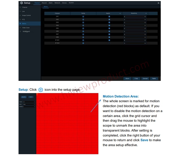
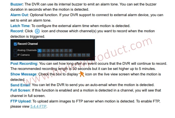
Switch: Enable or disable motion detection.
Sensitivity: Set the sensitivity level. Level 1 the lowest sensitivity level while level 8 is the highest
sensitivity level.
Click Alarm button to configure the motion detection alarm function:
5.1.6 PIR
This is an optional function. If your camera has PIR function, you can configure the PIR recording here.
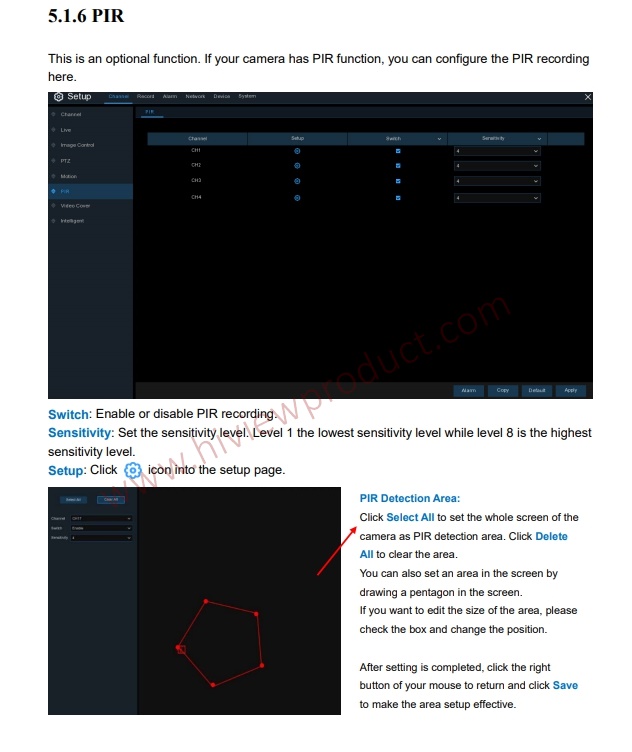
Click Alarm button to configure the PIR detection alarm function:
5.1.7 Video Cover
This menu allows you to create privacy zone(s) if you want to partially cover some certain part of the image. You can create up to 4 privacy zones in any size and location on the camera image.
Enable the Privacy Zone, and choose how many zones you need. The zone(s) appear as “red
box”. Click the edge of the red box and drag it to any size to create a privacy zone.

Note: The area of privacy zones you had set will be invisible in both live view & recording video.
5.1.8 Intelligent
The optional intelligent functions, including Perimeter Intrusion Detection, Line Crossing
Detection, Stationary Object Detection, Pedestrian Detection, Face Detection, and Cross
Counting.
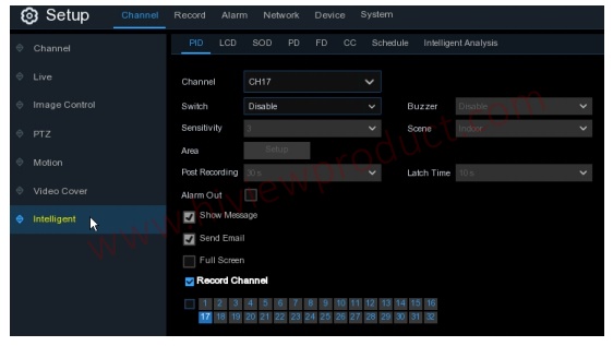
5.1.8.1 PID (Perimeter Intrusion Detection)
Perimeter Intrusion Detection function detects people, vehicle or other objects which enter and loiter in a pre-defined virtual region, and some certain actions can be taken when the alarm is triggered.
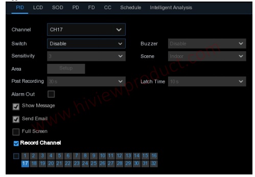
Channel: Select the channel you want to configure
Switch: Enable or disable the PID function
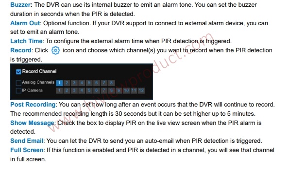
Buzzer: Disable or to active the buzzer to emit an alarm tone in 10, 20, 40 or 60 seconds when the
detection is triggered
Sensitive: The sensitivity level is from 1 to 4. Higher sensitivity will be easier to trigger
the detection.
Scene: Scene setting includes Indoor and Outdoor. Please choose the scene to
match with the place your camera installed.
Post Recording: You can set how long after an event occurs that the DVR will continue to record.
Latch Time: To configure the external alarm time when the detection is triggered.
Alarm Out: If your DVR support to connect to external alarm device, you can set to emit an alarm
tone.
Show Message: A letter “S” will be displayed on the screen when the PID function is triggered.
Send Email: If an alarm is triggered, an Email will be sent to your preset email account.
Full Screen: When the detection is triggered, the channel will be enlarged into full screen.
Record Channel: to select the channel(s) you want to record when a detection is triggered.
Area: Click [Setup] to draw a virtual region in the camera picture.
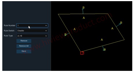
1. Choose one of the Rule Number. It is the number of PID area. Maximum 4 areas you can set for PID function.
2. To enable the detection in Rule Switch.
3. Choose a Rule Type.
AB: DVR will only detect the action from side A to side B;
BA: DVR will only detect the action from side B to side A;
AB: DVR will detect the action from either side B to side A or side A to side B.
4. Use your mouse to click 4 points in the camera picture to draw a virtual region. The sharp of the region should be a convex polygon. Concave polygon will be not able to save.
5. Click Save to save your settings.
6. If you want to modify the position or sharp of region, click the red box in the region, the borders of the region will be changed to red color. Long press the left button of your mouse to move the position of the region, or drag the corners to resize the region.
7. If you want to remove one of the regions from the camera picture, click the red box in the region and then click Remove button. Click Remove All will delete all regions.
Notice:
1) The perimeter shall not be too close to the edges/corners of the camera picture, since it may
fail to trigger the detection when the target pass through the edges/corners.
2) The shape of the regions shall not be too narrow/small, since it may fail to trigger the detection
when the target passes through outside the perimeter.

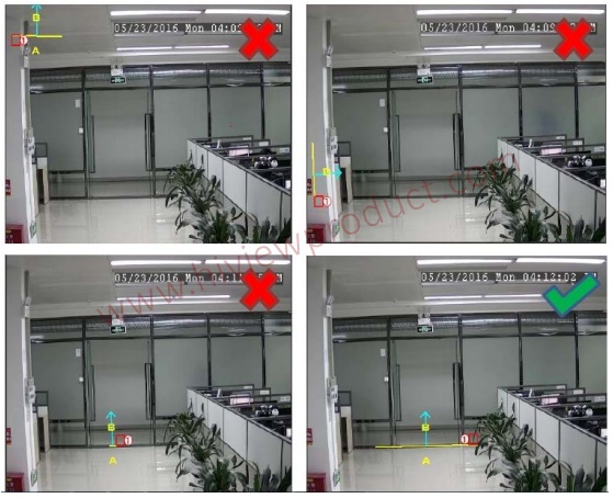
5.1.8.2 LCD (Line Crossing Detection)
Line Crossing Detection function detects people, vehicle or other objects which cross a pre-defined virtual line, and some certain actions can be taken when the alarm is triggered.
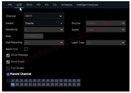
Channel: Select the channel you want to configure
Switch: Enable or disable the LCD function
Buzzer: Disable or to active the buzzer to emit an alarm tone in 10, 20, 40 or 60 seconds when the
detection is triggered
Sensitive: The sensitivity level is from 1 to 4. Higher sensitivity will be easier to trigger the
detection.
Scene: Scene setting includes Indoor and Outdoor. Please choose the scene to match with the
place your camera installed.
Post Recording: You can set how long after an event occurs that the DVR will continue to record.
Latch Time: To configure the external alarm time when the detection is triggered.
Alarm Out: If your DVR support to connect to external alarm device, you can set to emit an alarm
tone.
Show Message: A letter “S” will be displayed on the screen when the LCD function is triggered.
Send Email: If an alarm is triggered, an Email will be sent to your preset email account.
Full Screen: When the detection is triggered, the channel will be enlarged into full screen.
Record Channel: to select the channel(s) you want to record when a detection is triggered.
Area: Click [Setup] to draw a virtual line in the camera picture.
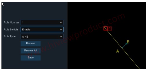
draw.
2. To enable the detection in Rule Switch.
3. Choose a Rule Type.
AB: DVR will only detect the action from side A to side B;
BA: DVR will only detect the action from side B to side A;
AB: DVR will detect the action from either side B to side A or side A to side B.
4. Use your mouse to click 2 points in the camera picture to draw a virtual line.
5. Click Save to save your settings.
6. If you want to modify the position or length of the line, click the red box in the line, the color of
the line will be changed to red color. Long press the left button of your mouse to move the line,
or drag the terminals to modify the length or position of the line.
7. If you want to remove one of the lines from the camera picture, click the red box in the line and
then click Remove button. Click Remove All will delete all lines.
Notice:
1) The lines shall not be too close to the edges of the camera picture, to avoid any failure to trigger
an alarm when the target cross through it.
2) The lines shall not be set too short, to avoid any failure to trigger an alarm when the target
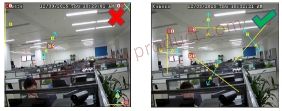
5.1.8.3 SOD (Stationary Object Detection)
Stationary Object Detection function detects the objects left over or lost in the pre-defined region such as the baggage, purse, dangerous materials, etc., and a series of actions can be taken when the alarm is triggered.
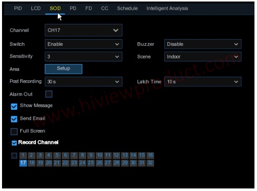
Channel: to select the channel you want to configure
Switch: to enable or disable the SOD function
Buzzer: to disable or to active the buzzer to emit an alarm tone in 10, 20, 40 or 60 seconds when
the detection is triggered
Sensitive: The sensitivity level is from 1 to 4, with a default value of 2. Higher sensitivity will be
easier to trigger the detection.
Scene: Scene setting includes Indoor and Outdoor. Please choose the scene to match with the
place your camera installed.
Post Recording: You can set how long after an event occurs that the DVR will continue to record.
Latch Time: To configure the external alarm time when the detection is triggered.
Alarm Out: If your DVR support to connect to external alarm device, you can set to emit an alarm
tone.
Show Message: A letter “S” will be displayed on the screen when the intelligent detection is
triggered.
Send Email: If an alarm is triggered, an Email will be sent to your preset email account.
Full Screen: When the detection is triggered, the channel will be enlarged into full screen.
Record Channel: to select the channel(s) you want to record when a detection is triggered.
Area: Click [Setup] to draw a virtual region in the camera picture.

1. Choose one of the Rule Number. It is the number of SOD area. Maximum 4 areas you can set
for SOD function.
2. To enable the detection in Rule Switch.
3. Choose a Rule Type.
Legacy: DVR will only detect the left-over objects;
Lost: DVR will only detect the lost objects;
Legacy & Lost: DVR will detect both left-over & lost objects.
4. Use your mouse to click 4 points in the camera picture to draw a virtual region. The sharp of
the region should be a convex polygon. Concave polygon will be not able to save.
5. Click Save to save your settings.
6. If you want to adjust the size of the region, click the red box in the region, the borders of the
region will be changed to red color. Long press the left button of your mouse to move the
whole region, or drag the corners to resize the region.
7. If you want to remove one of the regions from the camera picture, click the red box in the
region and then click Remove button. Click Remove All will delete all regions.
Notice:
1) The area for detection shall be greater than or equal to the size of the detected object, such as
the detection of a white bottle.
2) The detected object cannot be covered.
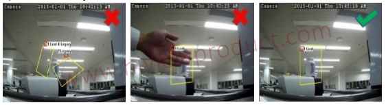
5.1.8.4 PD (Pedestrian Detection)
Pedestrian Detection function detects the moving people in a pre-defined region, and a series of actions can be taken when the alarm is triggered.
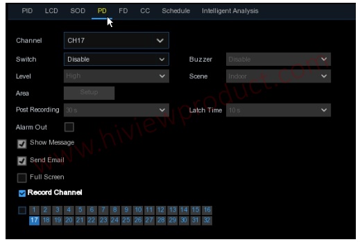
Channel: to select the channel you want to configure
Switch: to enable or disable the PD function
Buzzer: to disable or to active the buzzer to emit an alarm tone in 10, 20, 40 or 60 seconds when
the detection is triggered
Level: Small, Middle & Big. Small level is recommended to detect objects in long
distance. Big level is recommended to detect objects in short distance.
Scene: Scene setting includes Indoor and Outdoor. Please choose the scene to
match with the place your camera installed.
Post Recording: You can set how long after an event occurs that the DVR will continue to record.
Latch Time: To configure the external alarm time when the detection is triggered.
Alarm Out: If your DVR support to connect to external alarm device, you can set to emit an alarm
tone.
Show Message: A letter “S” will be displayed on the screen when the intelligent detection is
triggered.
Send Email: If an alarm is triggered, an Email will be sent to your preset email account.
Full Screen: When the detection is triggered, the channel will be enlarged into full screen.
Record Channel: to select the channel(s) you want to record when a detection is triggered.
Area: Click [Setup] to draw a virtual region in the camera picture.
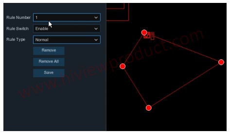
1.Choose one of the Rule Number. It is the number of PD area. Maximum 4 areas you can set
for PD function.
2. To enable the detection in Rule Switch.
3. Choose a Rule Type, only Normal available for this detection.
4. Use your mouse to click 4 points in the camera picture to draw a virtual region. The sharp of
the region should be a convex polygon. Concave polygon will be not able to save.
5. Click Save to save your settings.
6. If you want to adjust the size of the region, click the red box in the region, the borders of the
region will be changed to red color. Long press the left button of your mouse to move the
whole region, or drag the corners to resize the region.
7. If you want to remove one of the regions from the camera picture, click the red box in the
region and then click Remove button. Click Remove All will delete all regions.
Notice:
1) The region for detection shall not be in the area that people cannot reach.
2) The detected people should be completely surrounded in the region. 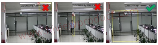
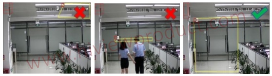
5.1.8.5 FD (Face Detection)
Face Detection function detects the faces of moving people appear in a pre-defined region, and a series of actions can be taken when the alarm is triggered.
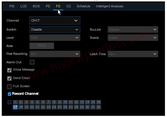
Channel: to select the channel you want to configure
Enable: to enable or disable the FD function
Buzzer: to disable or to active the buzzer to emit an alarm tone in 10, 20, 40 or 60 seconds when
the detection is triggered
Level: Small, Middle & Big. Small level is recommended to detect objects in long
distance. Big level is recommended to detect objects in short distance.
Scene: Scene setting includes Indoor and Outdoor. Please choose the scene to
match with the place your camera installed.
Post Recording: You can set how long after an event occurs that the DVR will continue to record.
Latch Time: To configure the external alarm time when the detection is triggered.
Alarm Out: If your DVR support to connect to external alarm device, you can set to emit an alarm
tone.
Show Message: A letter “S” will be displayed on the screen when the intelligent detection is
triggered.
Send Email: If an alarm is triggered, an Email will be sent to your preset email account.
Full Screen: When the detection is triggered, the channel will be enlarged into full screen.
Record Channel: to select the channel(s) you want to record when a detection is triggered.
Area: Click [Setup] to draw a virtual region in the camera picture.
1. Choose one of the Rule Number. It is the number of FD area. Maximum 4 areas you can set
for FD function.
2. To enable the detection in Rule Switch.
3. Choose a Rule Type, only Normal available for this detection.
4. Use your mouse to click 4 points in the camera picture to draw a virtual region. The sharp of
the region should be a convex polygon. Concave polygon will be not able to save.
5. Click Save to save your settings.
6. If you want to adjust the size of the region, click the red box in the region, the borders of the
region will be changed to red color. Long press the left button of your mouse to move the
whole region, or drag the corners to resize the region.
7. If you want to remove one of the regions from the camera picture, click the red box in the
region and then click Remove button. Click Remove All will delete all regions.
Notice:
1) The region for detection shall not be in the area that people cannot reach.
2) The region should include the complete front face.
5.1.8.6 CC (Cross-Counting)
Cross-Counting function counts the times for moving objects or people across the virtual lines.
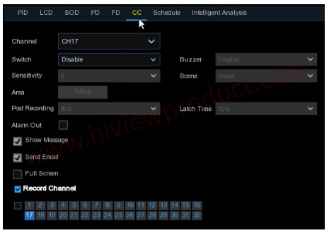
Channel: to select the channel you want to configure
Switch: to enable or disable the CC function
Buzzer: to disable or to active the buzzer to emit an alarm tone in 10, 20, 40 or 60 seconds when
the detection is triggered
Sensitive: The sensitivity level is from 1 to 4, with a default value of 2. Higher sensitivity will be
easier to trigger the detection.
Scene: Scene setting includes Indoor and Outdoor. Please choose the scene to match with the
place your camera installed.
Post Recording: You can set how long after an event occurs that the DVR will continue to record.
Latch Time: To configure the external alarm time when the detection is triggered.
Alarm Out: If your DVR support to connect to external alarm device, you can set to emit an alarm
tone.
Show Message: A letter “S” will be displayed on the screen when the intelligent detection is
triggered.
Send Email: If an alarm is triggered, an Email will be sent to your preset email account.
Full Screen: When the detection is triggered, the channel will be enlarged into full screen.
Record Channel: to select the channel(s) you want to record when a detection is triggered.
Area: Click [Setup] to draw a virtual region in the camera picture.
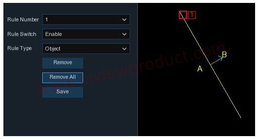
lines.
2. To enable the detection in Rule Switch.
3. Choose a Rule Type
Object: Will count for only moving objects.
Pedestrian: Will count only moving people.
4. Use your mouse to click 2 points in the camera picture to draw a virtual line. From Side A to
Side B is Enter, from Side B to Side A is Exit.
5. Click Save to save your settings.
6. If you want to modify the position or length of the line, click the red box in the line, the color of
the line will be changed to red color. Long press the left button of your mouse to move the line, or drag the terminals to modify the length or position of the line.
7. If you want to remove one of the lines from the camera picture, click the red box in the line and
then click Remove button. Click Remove All will delete all lines.
Notice:
1) The lines shall not be too close to the edges of the camera picture, to avoid any failure to trigger an alarm when the target cross through it.
2) The lines should be in the area that detected object can be reach.
3) The lines shall not be set too short, to avoid any failure to trigger an alarm when the target
passes outside it.
You are able to search & view the statistical result of cross counting in 5.1.8.7 Intelligent Analysis.
5.1.8.7 Intelligent Analysis
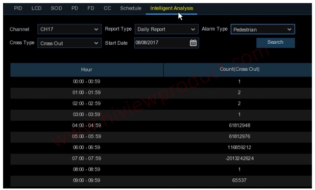
The statistical result can be queried by Daily / Weekly / Monthly / Annual for Cross In & Cross Out.
5.1.8.8 Intelligent Schedule
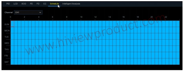
In order to active the intelligent function, you need to config the schedule. The schedule will be
active in 24 hours x 7 days.
To set the schedule, choose one channel then drag the cursor to mark the slots. The sky-blue
blocks in the time slots will be active for Intelligent detections. The schedule is valid only for the
selected channel each time when you set. If you want to use the same schedule for other channels,
use Copy function. Click Save to save your settings.
5.2 Record
This menu allows you to configure the recording parameters
5.2.1 Encode
This menu allows you to configure the recording video or network transmission picture quality.
Generaly, Mainstream defines the recording video quanlity which will be saved in the HDD;
Substream defines the video quality which is being viewed via remote access, for example web
client & CMS; Mobilestream defines the video quality which is being viewed via remote access via
mobile devices.

Resolution: This parameter defines how large the recorded image will be.
FPS: This parameter defines the number of frames per second the DVR will record.
Video Encode Type: For IP camera only. DVR support H.264 IP camera only. If you choose H.265,
live view screen of the IP channel will display “Decoding Failed”.
Bitrate Control: Select the bitrate level. For a simple scene, such as a gray wall is suitable
constant bitrate (CBR). For more complex scene, such as a busy street is suitable variable bitrate
(VBR).
Bitrate Mode: If you want to set the bitrate by yourself, then choose User-defined mode. If you
want to select the predefined bitrate, choose Predefined mode.
Bitrate: This parameter corresponds to the speed of data transfer that the DVR will use to record
video. Recordings that are encoded at higher bitrates, will be of better quality.
Audio: Select this option if you want to record audio along with video and have a microphone
connected to the DVR or using a camera with audio capability.
AMR: If AMR option is checked, this channel will be recorded in maximum frame rate & bitrate
when an alarm (motion or I/O alarm) happens to this channel.
5.2.2 Record
This menu allows you to configure the channel recording parameters.
5.2.2.1 Record
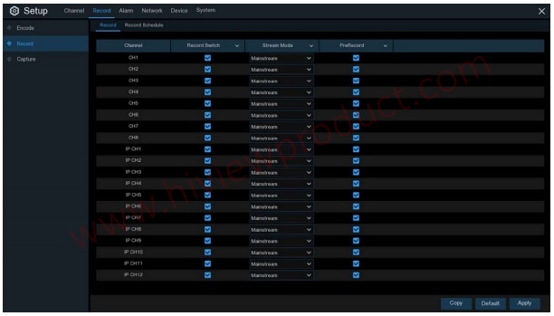
Record Switch: Check to enable the recording in this channel.
Stream Mode: Choose the recording quality. If you choose Dualstream, the system will record in
both Mainstream & Substream.
PreRecord: If this option is enabled, the DVR starts recording a few seconds before an alarm
event occurs. Use this option if your primary recording type is motion or I/O alarm based.
5.2.2.2 Record Schedule
This menu allows you to specify when the DVR records video and defines the recording mode for each channel. The recording schedule lets you set up a schedule like, daily and hourly by normal (continuous) recording, motion recording, I/O alarm recording & PIR recording (if your DVR supports). To set the recording mode, click first on the mode radio button (Normal, Motion, IO, PIR), then drag the cursor to mark the slots. The recording schedule is valid only for one channel. If you want to use the same recording schedule for other channels, use Copy function. Click Apply to
save your settings.
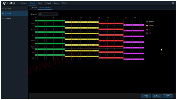
Channel: Select the channel to set its recording parameters.
Normal: When the time slot is marked green, this indicates the channel performs normal recording
for that time slot.
Motion: When the time slot is marked yellow, this indicates the channel records only when a
motion is detected during that time slot.
IO: When the time slot is marked red, this indicates the channel records only when the sensor is
triggered during that time slot.
PIR: When the time slot is marked purple, this indicates the channel records only when the PIR is
triggered during that time slot.
No Record: A time slot marked black means that there is no recording scheduled for the time slot.
5.2.3 Capture
This menu allows to configure the image capture function.
5.2.3.1 Capture
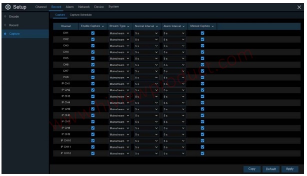
Enable Capture: Enable or disable automatic capturing on the channel.
Stream Type: Select the image resolution by mainstream or substream.
Normal Interval: Time interval to capture an image in normal recording.
Alarm Interval: Time interval to capture an image when motion, IO alarm or PIR is triggered
Manual Capture: Enable or disable manual capture in the channel
5.2.3.2 Capture Schedule
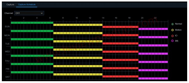
Channel: Select the channel to set its capture parameters.
Normal: When the time slot is marked green, this indicates the channel performs normal capture
for that time slot.
Motion: When the time slot is marked yellow, this indicates the channel capture images only when
a motion is detected during that time slot.
IO: When the time slot is marked red, this indicates the channel capture images only when the
sensor is triggered during that time slot.
PIR: When the time slot is marked purple, this indicates the channel capture images only when the
PIR is triggered during that time slot.
No Capture: A time slot marked black means that it won’t capture any images for the time slot, but
you can manually capture images if you enable the manual capture function in the channel.
5.3 Alarm
In these section, you can configure the alarm parameters.
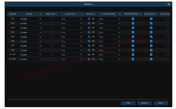
5.3.1 Motion
Operation is same as 5.1.5 Motion
5.3.2 I/O
This is an optional function, it will appear if your DVR supports sensor I/O, you connect external
sensor I/O alarm devices to work with the DVR.
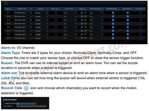
Post Recording: You can set how long alarm record will last when alarm ends (30s, 1minutes,
2minutes, 5minutes).
Show Message: Display the alarm messages on the screen when sensor is triggered.
Send Email: Set to send email to specified email when sensor is triggered.
Full Screen: When sensor is triggered, the corresponding channel will be switched to the full
screen mode.
FTP Upload: To upload alarm images to FTP server when I/O alarm is triggered. To enable FTP,
please view 5.4.4 FTP.
5.3.3 PIR
Operation is same as 5.1.6 PIR
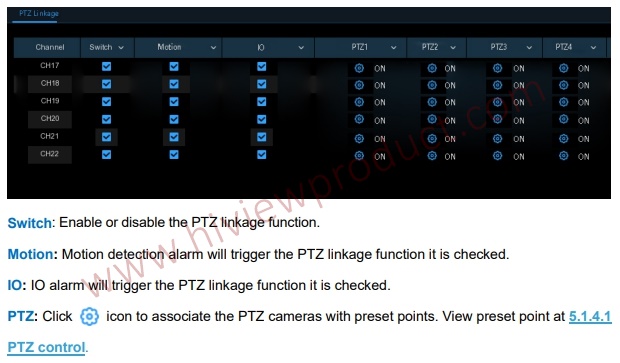
5.3.4 PTZ Linkage
If you had connected the PTZ cameras, you can set the linkage between PTZ cameras and Motion
Alarm and/or external I/O sensor alarm. With the linkage function, you can turn your PTZ cameras
focus to the preset point when a motion or I/O alarm happens.
5.3.5 Exception
This menu allows you to set the type of events that you want the DVR to inform you
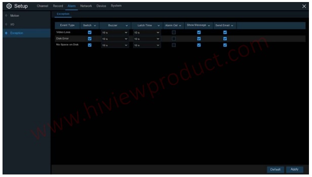
Event Type: Select the event type from below options:
- No Space on Disk: When an HDD is full.
- Disk Error: If the HDD is not detected properly.
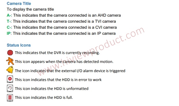
- Video Loss: If a camera is not connected properly.
Switch: Check the box to enable the monitoring of the event.
Buzzer: Set the buzzer duration when the event occurs (Off/10s/20s/40s/60s). To disable buzzer,
select OFF.
Latch Time: This is an optional function. Determine how long the external alarm device to sound
(10s, 20s, 40s, 60s) if your DVR support to connect external alarm device.
Alarm Out: This is an optional function. Click to enable the external alarm device to sound. This is
an optional function.
Show Message: Check the box to display a message on the screen when No Space on Disk, Disk
Error, or Video Loss event happens.
Send Email: Let the DVR to send you an auto-email when an event occurs.
5.4 Network
This menu allows you to configure network parameters, such as PPPoE, DHCP, and 3G. The most
common types are DHCP. Most probably your network type is DHCP, unless the network is
manually addressed. If you need an authentication user name and password to the Internet, then
choose PPPoE. If you want to use mobile network connection, then choose 3G.

5.4.1 General
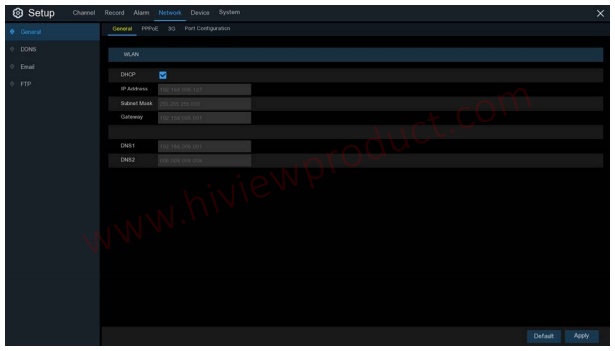
If you connect to a router allows to use DHCP, please check the DHCP box. The router will assign
automatically all the network parameters for your DVR. Unless the network is manually addressed
below parameters:
IP Address: The IP address identifies the DVR in the network. It consists of four groups of
numbers between 0 to 255, separated by periods. For example, “192.168.001.100”.
Subnet Mask: Subnet mask is a network parameter which defines a range of IP addresses that
can be used in a network. If IP address is like a street where you live then subnet mask is like a
neighborhood. The subnet address also consists of four groups of numbers, separated by periods.
For example, “255.255.000.000”.
Gateway: This address allows the DVR to access the Internet. The format of the Gateway
address is the same as the IP Address. For example, “192.168.001.001”.
DNS1/DNS2: DNS1 is the primary DNS server and DNS2 is a backup DNS server. Usually should
be enough just to enter the DNS1 server address.
5.4.4.1 PPPoE
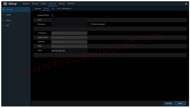
This is an advanced protocol that allows the DVR to connect to the network more directly via DSL
modem.
Check the “Enable PPPOE” box, and then enter the User name & Password of the PPPoE.
Click Apply to save, system will reboot to active the PPPoE setting.
5.4.1.2 3G
This is a prior using the mobile network, you need to connect a 3G dongle to the DVR
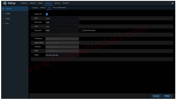
Enable the 3G option, enter the APN, Dial Code, User name & password according to the
instruction of your 3G dongle device.
Prior using the mobile network, you need to connect a 3G dongle to the DVR
5.4.1.3 Port Configuration
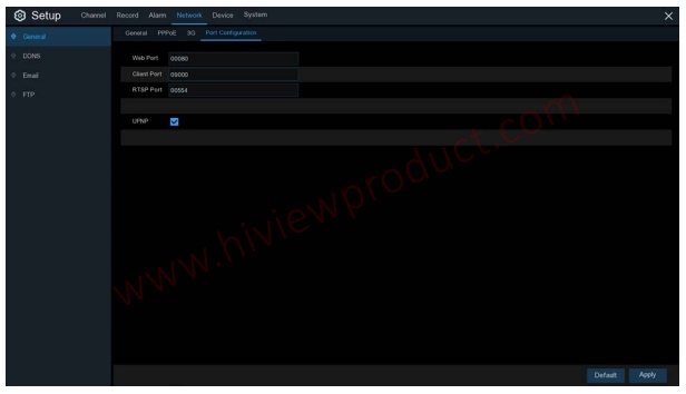
Web Port: This is the port that you will use to log in remotely to the DVR (e.g. using the Web
Client). If the default port 80 is already taken by other applications, please change it.
Client Port: This is the port that the DVR will use to send information through. If the default port
9000 is already taken by other applications, please change it.
RTSP Port: Default is 554, if the default port 554 is already taken by other applications, please
change it.
UPNP: If you want to log in remotely to the DVR using Web Client, you need to complete the port
forwarding. Enable this option if your router supports the UPnP. You need to enable UPnP both, on
DVR and router. In this case, you do not need to configure manually port forwarding on your router.
If your router does not support UPnP, make sure the port forwarding is completed manually
5.4.2 DDNS
This menu allows you to configure DDNS settings. The DDNS provides a static address to simplify
remote connection to your DVR. To use the DDNS, you first need to open an account on the
DDNS service provider’s web page.
DDNS: Check to enable DDNS.
Server: Select the preferred DDNS server (DDNS_3322, DYNDNS, NO_IP, CHANGEIP,
DNSEXIT).
Domain: Enter the domain name you created on the DDNS service provider’s web page. This will
be the address you type in the URL box when you want to connect remotely to the DVR via PC.
Fox example: dvr.no-ip.org.
User/Password: Enter the user name and password you obtained when creating an account on
the DDNS service provider’s web page.
After all parameters are entered, click Test DDNS to test the DDNS settings. If the test result is
“Network is unreachable or DNS is incorrect”, please check whether the network works fine, or the
DDNS information is correct or not.
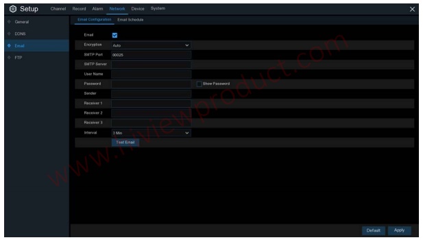
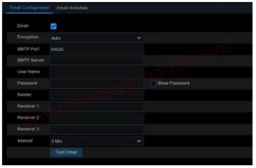
5.4.3 Email
This menu allows you to configure email settings. Please complete these settings if you want to
receive the system notifications on your email when an alarm is triggered, HDD becomes full, HDD
is in error state, or Video Loss occurs.
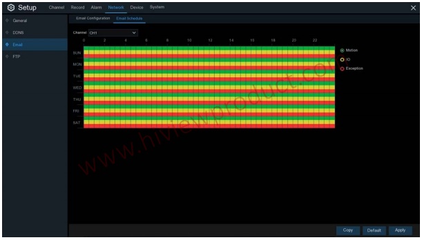
The color codes on email schedule have the following meanings:
Green: Slot for Motion detection.
Yellow: Slot for I/O Alarm (optional).
Red: Slot for Exception (HDD full, HDD error, or Video Loss).
Purple: Slot for PIR (optional)
5.4.4 FTP
This menu allows you to enable FTP function to view and load captured snapshots from DVR to
your storage device over FTP.
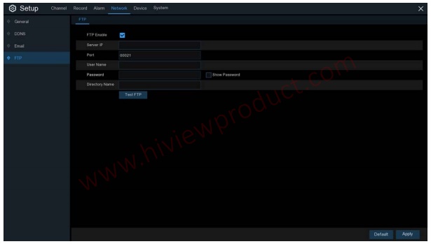
FTP Enable: Click to enable FTP function.
Server IP: Enter your FTP server IP address or domain name.
Port: Enter the FTP port for file exchanges.
Name/ Password: Enter your FTP server user name and password.
Directory Name: Enter the default directory name for the FTP file exchanges.
Test FTP: Click to test the FTP settings.
5. 5 Device
In this section, you can configure the internal HDD & Cloud storage function.
5. 5.1 Disk
This menu allows you to check & configure the internal HDD(s). You need to format the HDD only
at the first startup and if you replace a new HDD.
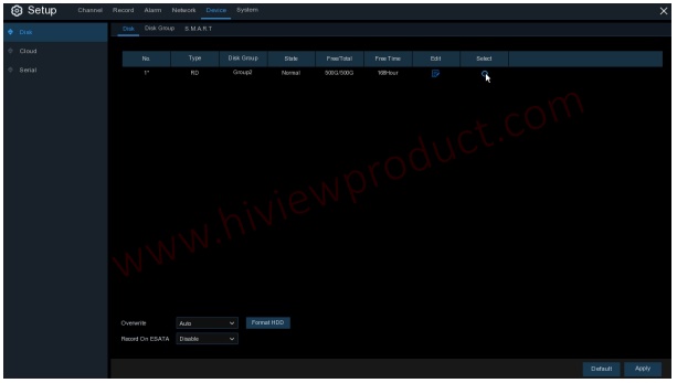
Format HDD: Select the HDD you want to format and then click Format HDD. To start formatting,
you need to enter your user name and password and then click OK to confirm to continue
formatting.
Overwrite: Use this option to overwrite the old recordings on the HDD when the HDD is full. For
example, if you choose the option 7 days then only the last 7 days recordings are kept on the HDD.
To prevent overwriting any old recordings, select OFF. If you have disabled this function, please
check the HDD status regularly, to make sure the HDD is not full. Recording will be stopped if HDD
is full.
Record on ESATA: This menu only displayed when your DVR is coming with an e-SATA port on
the rear panel. It will allow to record the video to external e-SATA HDD to enhance your HDD
capacity. If the e-SATA recording function is enabled, e-SATA backup function will be disabled.
If your DVR supports to install multiple HDDs, the edit icon appears in your system, you can click it
to edit the HDD as below:
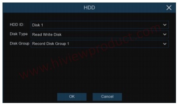
Disk Type: Read-write, read-only, and redundant.
Read-write mode is the normal status for a HDD to save recording or search recording to play.
To prevent important video data from being overwritten during cyclic recording, the HDD can be
set as Read-only mode. New recording will be not able to save into this read-only HDD. You can
still search recording from this read-only HDD to play.
A Redundant HDD can be used to automatically backup video footage on the recording
(read-write) hard drive. When a redundant HDD is set, the system can be set to record cameras in
parallel to both the recording hard drive and the redundant hard drive in case of hard drive failure.
5.5.1.1 Disk Group
If your DVR supports to install multiple HDDs, you can configure the HDD to be different groups.
HDD groups allow you to balance recordings across multiple hard drives. For example, you can
record channels 1~4 to one hard drive and 5~8 to a second hard drive. This can reduce the
amount of wear on the hard drives and may extend the life of the hard drives.
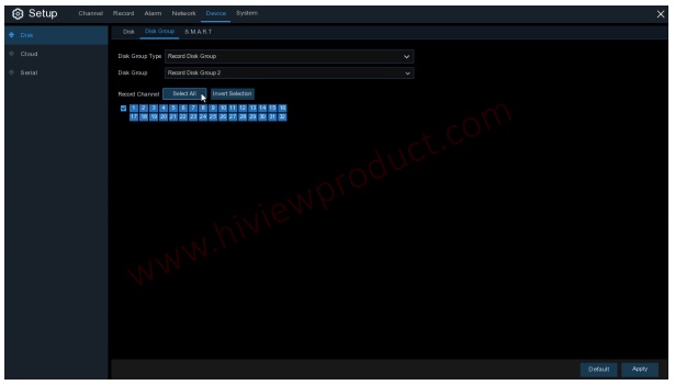
2. Use the dropdown next to Disk Group to select the specific group within the selected group
type.
3. Click the numbered boxes representing channels to record channels to HDDs in the selected
group.
4. Click Apply to save.
5.5.1.2 S.M.A.R.T
This function can be used to display technical information on the hard drive installed inside your
DVR. You can also perform a test (there are three types available) to evaluate and detect potential
drive errors.

developed a fault (such as one or more bad sectors), you can instruct your DVR to continue saving
to the drive.
Self-check Type: There are three types available:
Short: This test verifies major components of the hard drive such as read/write heads, electronics
and internal memory.
Long: This is a longer test that verifies the above as well as performing a surface scan to reveal
problematic areas (if any) and forces bad sector relocation
working.
Note: When performing a test, your DVR will continue to work as normal. If an HDD S.M.A.R.T
error found, the HDD can be continued to use, but there will be a risk to lose recording data. It is
recommended to replace a new HDD.
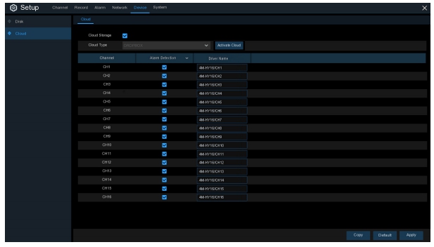
5.5.2 Cloud
Your DVR has the ability to upload snapshots to the cloud service via Dropbox which is a free
service that allows you to easily store and share snapshots and always have them on hand when
you need them.
working.
Note: When performing a test, your DVR will continue to work as normal. If an HDD S.M.A.R.T
error found, the HDD can be continued to use, but there will be a risk to lose recording data. It is
recommended to replace a new HDD.
5.5.2 Cloud
Your DVR has the ability to upload snapshots to the cloud service via Dropbox which is a free
service that allows you to easily store and share snapshots and always have them on hand when
you need them.
same email address and password used for your DVR. Go to www.dropbox.com, input your name,
email address and password, agree to the terms & conditions then click the sign up button.
Cloud Storage: Check to enable the function.
Cloud Type: Only Dropbox is supported currently.
Alarm Detection: Enable if you want to upload snapshots to Dropbox when the camera detects a
motion or triggered by I/O alarm.
Activate Cloud: Click to activate the function. After a short moment, you will see a message
on-screen. An activation link has been sent to your email (the email address which you had set to
receive email alerts in 5.4.3 Email). Check your email then click the link to activate. You will be
taken to the Dropbox website. Click “Allow” to finalize the activation. Repeat these steps if you
would like to enable cloud storage for the other cameras available.
5.6 System
Change general system information such as date, time and region, edit passwords and
permissions, and more.
5.6.1 General
numbers.
Device ID: Enter the desired ID for your DVR. The device ID is used to identify the DVR, and can
only be composed of numbers. For example, 2pcs DVRs are installed in the same place, the
Device ID is 000000 for one of the DVRs, and 111111 for another DVR. When you want to operate
the DVR with a remote controller, both of the DVR may receive the signal from controller & act at
the same time. If you want to control only the DVR with ID 111111, you can input the Device ID
111111 in login page with remote controller for further operations.
languages are available.
Video Format: Select the correct video standard for your region.
Menu Timeouts: Click the drop-down menu to select the time your DVR will exit the Main Menu
when idle. You can also disable this by selecting “OFF” (password protection will be temporarily
disabled).
Mode: XVR or DVR. XVR model will allow you to add IP Cameras to the DVR. If you change the
mode from XVR to DVR, all added IP cameras will be deleted.
Show Wizard: Click the checkbox if you would like to display the Startup Wizard each time you
turn on or reboot your DVR.
5.6.1.1 Date and Time
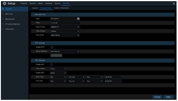
Date: Click the calendar icon to change the date.
Time: Click the dialogue box to change the time.
Date Format: Select the preferred date format.
Time Format: Select the preferred time format.
Time Zone: Select a time zone relevant to your region or city.
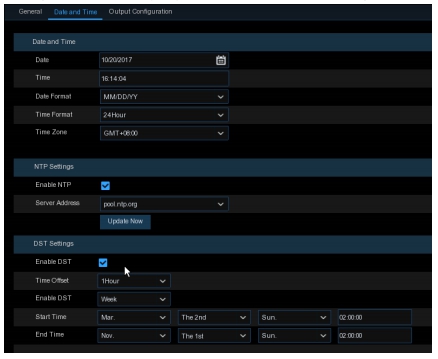
The NTP (Network Time Protocol) function allows your DVR to automatically sync its clock with a
time server. This gives it the ability to constantly have an accurate time setting (your DVR will
periodically sync automatically).

Address, click Update Now to manually sync
the date & time.
Click Apply to save your settings.
When NTP function is enabled system will
The DST (Daylight Saving Time) function allows you to select the amount of time that Daylight
Saving has increased by in your particular time zone or region.
This refers to the difference in minutes, between Coordinated Universal Time (UTC) and the local
time.
Enable DST: You can select how Daylight Saving starts and ends:
Week: Select the month, a particular day and time when Daylight Saving starts and ends. For
example, 2 a.m. on the first Sunday of a particular month.
Date: Select the start date (click the calendar icon), end date and time when Daylight Saving starts
and ends.
Start Time / End Time: Set the start time and end time for Daylight Saving.
5.6.2 Output Configuration
This menu allows you to configure video output parameters.
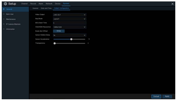
LIVE-OUT is used to configure the main output parameters.
SPOT-OUT is an optional option to config the VGA spot output parameters.
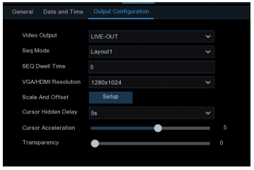
SEQ Mode: Select how many video channels you would like to display when your DVR is in
sequence mode.
SEQ Dwell Time: Enter in seconds the maximum length of time you would like to display a video
channel in sequence mode before displaying the next video channel (300 seconds is the
maximum).
Output Resolution: Select a display resolution that is suitable for your TV. 1920 x 1080 will suit
most TVs. If your DVR supports 4K output resolution, you can select either 2K (2560 x 1440) or 4K
(3840 x 2160) to take advantage of the higher resolution that your 4K TV provides.
Scale and Offset: The DVR supports to adjust the size & position of the display screen to match
your monitor or TV. Click Setup button to adjust
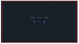
screen by scale.
X Offset: To move the displayed screen to left
or right.
Y Offset: To move the displayed screen to up or
down.
or you can scroll the wheel of the mouse to adjust. Click the right button of your mouse to exit, and
click Apply to save your modifications.
Cursor Hidden Delay: Click the drop-down menu to select the time your DVR will hide the mouse
cursor when idle. You can also disable this by selecting “OFF” (password protection will be
temporarily disabled).
Cursor Acceleration: To adjust the speed to move the mouse cursor.
Transparency: Click and hold the slider left or right to change how transparent the Menu Bar and
Main Menu will appear on-screen. Adjust accordingly
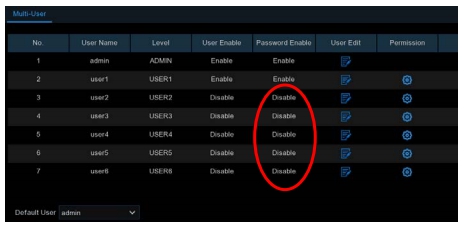
This menu allows you to configure the user name, password and user permission.
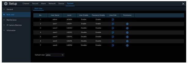
• ADMIN — System Administrator: The administrator has full control of the system, and
can change both administrator and user passwords and enable/disable password
protection.
• USER — Normal User: Users only have access to live viewing, search, playback, and
other functions. You may set up multiple user accounts with varying levels of access to the
system.
5.6.3.1 Changing Password
To change the password for the administrator or user accounts, click the User Edit icon . The
password has to be a minimum of 8 characters and can contain a mixture of numbers and letters.
Enter your new password again to confirm, and then click Save to save your new password. You
will be required to input your old password to authenticate.
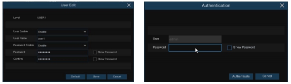
you want to disable the password protection, please ensure your DVR is placed in a secure place.
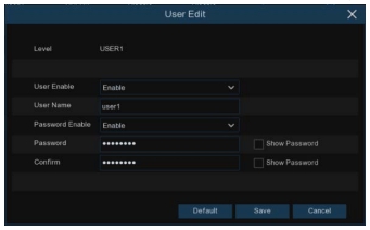
3. Click the field next to User Name to change the user name for the account.
4. Select Enable from the drop-down next to Password Enable.
5. Click the field next to Password to enter the desired password.
6. Click the field next to Confirm to reenter the password.
7. Click Save. You will be required to input your Admin password to authenticate.
5.6.3.3 Setting User Permissions
The administrator account is the only account that has full control of all system functions. You can
enable or disable access to certain menus and functions of each user account.
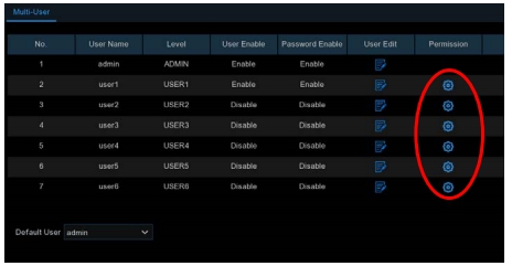
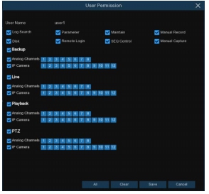
access. Click All to check all boxes. Click Clear to check none of the boxes.
3. Click Save to save your modifications.
In this section, you will be able to search & view the system log, load default settings, upgrade the
system, export & import system parameters and manager system auto reboot.
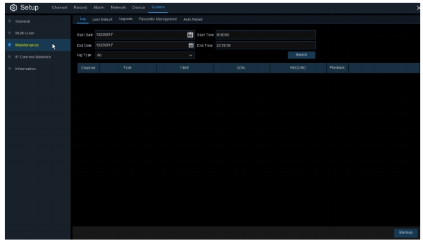
The system log shows you important system events, such as motion alarms and system
warnings. You can easily create a backup file of the system log for a set time period to a USB
flash drive
1. Click the field next to Start Date & Start Time to choose the starting date & time for your
search from the on-screen calendar.
2. Click the field next to End Date & End Time to choose the end date & time for your search from
the on-screen calendar.
3. Select the type of events you would like to search for from the dropdown next to Log Type, or
select All to see the entire system log for the selected time period.
4. Click Search.
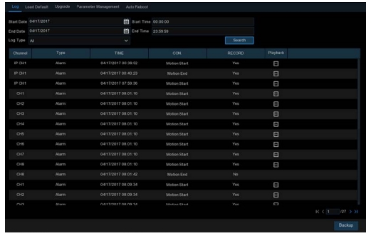
5. Browse system log events from your search period:
o Video events can be played back instantly by clicking in the Playback column. Right-click to
return to your search results.
o Use the / buttons in the bottom-right corner of the menu to move between pages
of system log events.
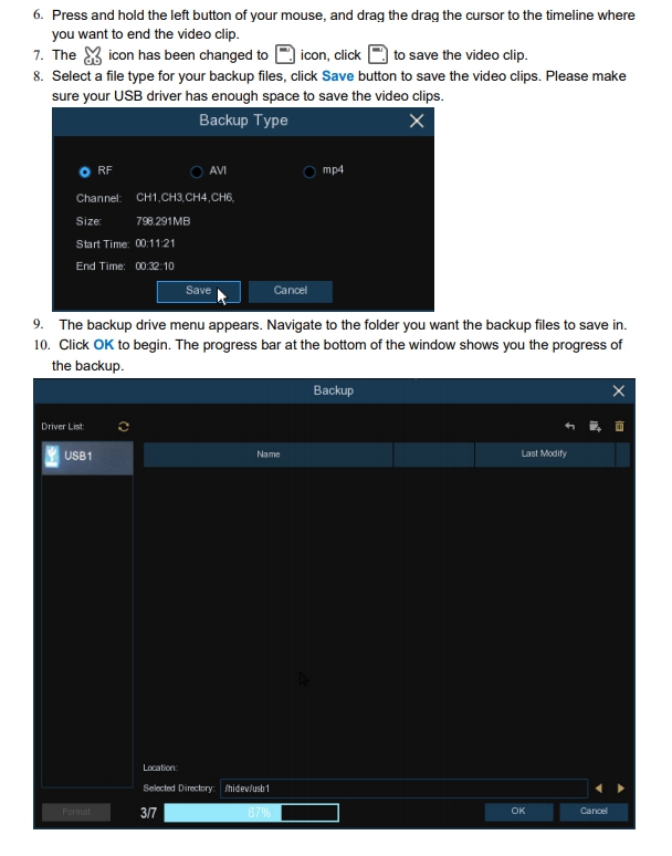
6. Click Backup to create a backup of the system log for your search period. Please make sure
your flash derive has been connected to the DVR’s USB port.
7. The backup drive menu appears. Navigate to the folder you want the backup file to be saved in,
then click OK to begin.
5.6.4.2 Load Default
Reset the DVR settings to its out-of-box state. You can choose to reset all settings at once, or just
settings on specific menus. Restoring default settings will not delete recordings and snapshots
saved to the hard drive.
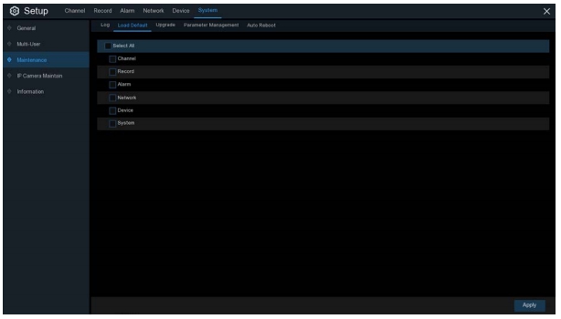
default settings of your chosen items.
5.6.4.3 Upgrade
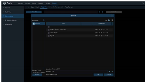
USB port.
2. Click Select File button to choose the firmware file in your USB flash drive, then Click OK.
3. Click Upgrade button to start system upgrade. The system upgrade will last around 5-10
minutes, please do NOT power off the DVR or remove the USB from DVR during firmware
upgrade.
5.6.4.4 Parameter Management
You can export the main menu settings you have configured to a USB flash drive, or import an
exported setting file from USB flash drive to the DVR.

required to input the Admin password to authenticate.
Load Settings: Once you have created a system settings export, you can import the settings on
another DVR. Click Load Settings button to navigate to the system settings file you want to
import from your USB flash driver. You will be required to input the Admin password to
authenticate.
This menu allows the system to auto reboot the DVR regularly. It is recommended to leave this
function enabled, as it maintains the operational integrity of your DVR.
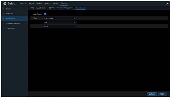
Time: You can set the DVR to reboot by day, week or month.
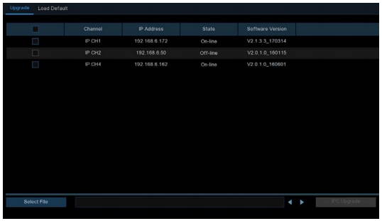
5.6.5 IP Camera Maintain
This menu allows you to upgrade the IP camera’s firmware and restore default settings of IP
camera.

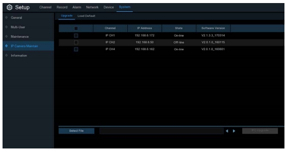
2. Click Select File select the update file from your USB flash drive, then click OK.
3. Click IPC Upgrade button to start upgrading. You will be required to input the Admin password
to authenticate. Please do NOT power off the DVR and IP camera or remove the USB during
the upgrading.
5.6.5.2 Load Default Settings for IP Camera
2. Click Load Default to restore settings. You will be required to input the Admin password to
authenticate.
This menu allows you to view the system information, channel information, record information &
network status.
5.6.6.1 Information
View system information such as device ID, device model name, IP address, MAC address,
firmware version and more.
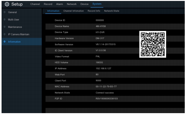
page. You can scan this QR cord with mobile app to remote view the DVR.
5.6.6.2 Channel Information

recording specifications, motion detection status & privacy zone.
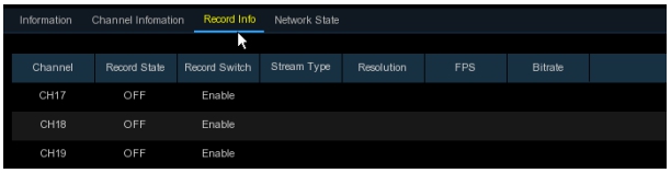
View recording information for each connected camera such as bitrate, stream type, recording
resolution and frame rate (FPS).
5.6.6.4 Network State
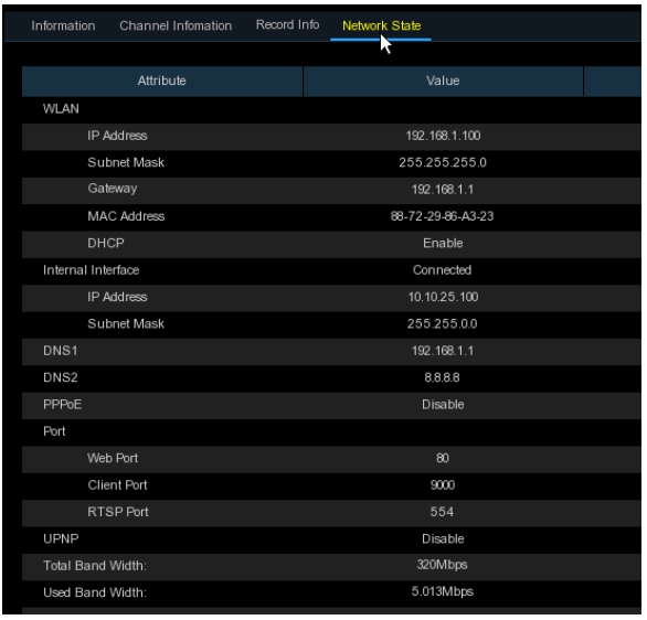
Total Band Width: It shows the DVR’s total input band width for IP cameras.
Used Band Width: It shows the used band width of IP cameras.
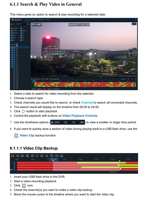
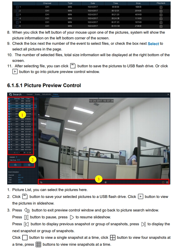
The Search function gives you the ability to search for and play previously recorded videos as well
as snapshots that are stored on your DVR’s hard drive. You have the choice of playing video that
matches your recording schedule, manual recordings or motion events only. The Backup function
gives you the ability to save important events (both video and snapshots) to a USB flash drive.
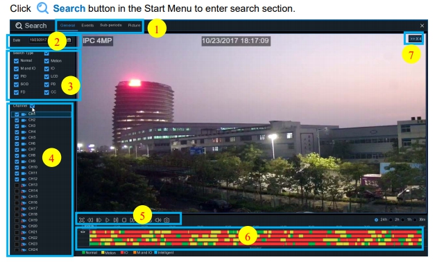
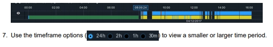
Sub-periods, Smart & Pictures
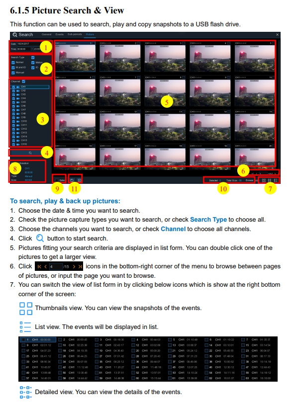
2. Search Date: search by a date to play back.
3. Search Type: the system provides different search types to narrow your search.
4. Channel Selection: to choose the channels you want to search & play.
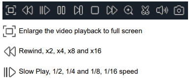
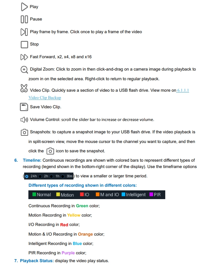
5. Video Playback Controls: to control the video playback.

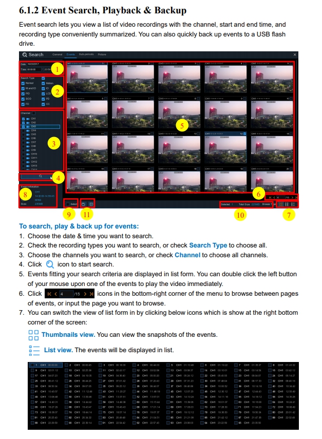
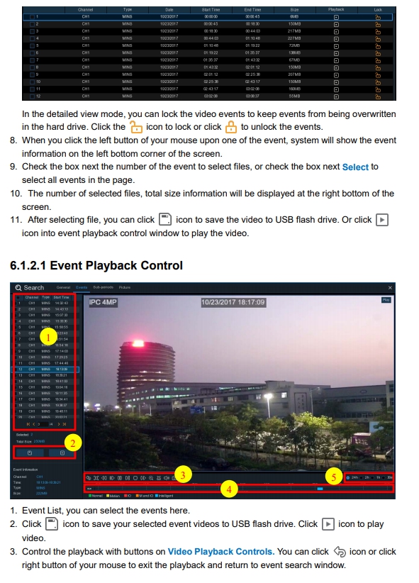
 6.1.2 Event Search, Playback & Backup
Event search lets you view a list of video recordings with the channel, start and end time, and
recording type conveniently summarized. You can also quickly back up events to a USB flash
drive.
Smart mode allows you to easily search & play the motion events in one or more specific areas of
the channel.
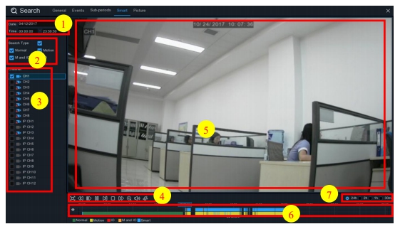
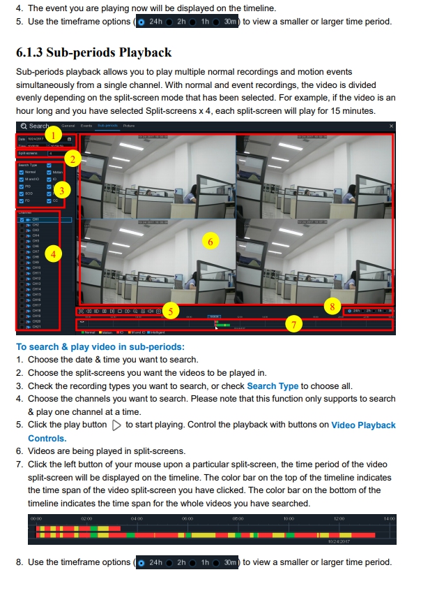
1. Choose the date & time you want to search.
2. Check the recording types you want to search, or check Search Type to choose all.
3. Choose the channel you want to search, the motion recording in the selected channel will be
searched automatically. Please note that this function only supports to search & play one
channel at a time.
4. Click the play button on the to start playing. Control the playback with buttons on Video
Playback Controls.
5. Videos are being played in the screen.
6. The color bar on the top of the timeline indicates the time span of the motion recordings you
have searched. The color bar on the bottom of the timeline indicates the complete time span for
the whole recordings you have specified.
The smart search function searches the motion recordings in the whole area of channel by default.
You can specify one or more particular areas to narrow your search.
Click this icon on Video Playback Controls, the camera will be shown in full screen and the
Smart controls bar will be visible.
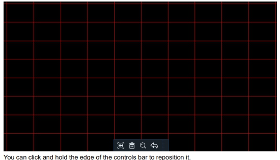
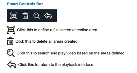
1. Click and drag to select the area that you want to define. Multiple areas can be defined. You
can also use the same action to remove sections of the defined area or to delete it entirely.
When finished, click the search button to play video based on the areas defined.
2. You’ll be returned back to the playback interface. Segments matching your search criteria will
be shown on the timeline in blue color.
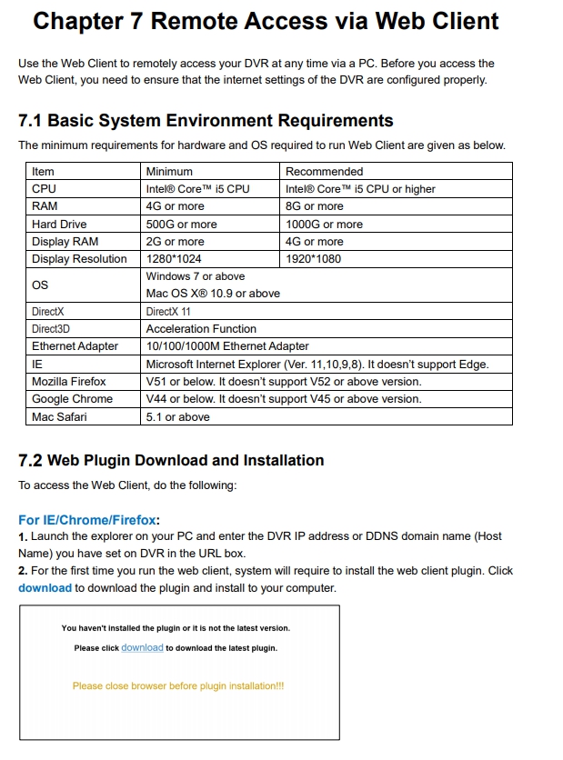
This function can be used to search, play and copy snapshots to a USB flash drive.
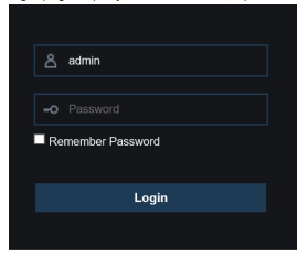
login page. Input your user name and password to login the web client.
need to enable NPAPI plugins. Please enter chrome://flags/#enable-npapi on URL bar to find and
enable NPAPI. It doesn’t support V45 or above so far.

The web client supports to fully control the DVR with administrator account. Please make sure to
protect your user name & password for preventing illegal login.
7.3.1 Live Interface
This is the first screen that opens after you have logged in to the Web Client. Here you can open or
close live preview, record video to local computer manually, take snapshots of the screens, PTZ
control, color adjustment, etc.

Mainstream: View all live videos using high-quality mainstream video settings.
Substream: View all live videos using middle-quality substream video settings.
Mobile Stream: View all live video using lower-quality mobile stream video settings to
conserve bandwidth. Available for IP channels only.
3- Main Menus:
Live: View live video from cameras.
Playback: View recorded video which is saved in DVR’s HDD.
Remote Setting: Access functions of the DVR setting menus.
Local Settings: Set download locations for recordings and snapshots taken using Web Client,
and choose file type for video files.
4- Information: Hover over to see system details.
5- Exit.
6- Color Controls. Click to display or hide the color controls.

8- PTZ Controls

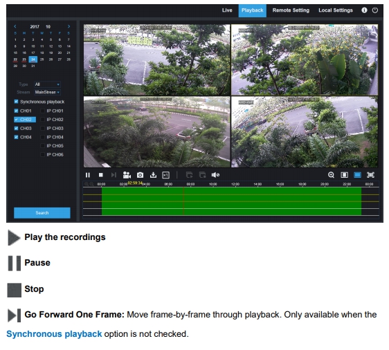
1. Click Playback in the top-right corner of the window.
2. Select a day on the calendar to search for recordings from. Days with recordings appear with
a red underline.
3. Select the recording type to search for from the dropdown next to Type, or select All to
search for all recordings.
4. To choose the video stream you want to search & play. If you want to play Substream
recordings, please make sure you had set the DVR to record with Dualstream at 5.2.2.1
Record.
5. Check the channels you would like to search for recordings from. Check Synchronous
playback to play all channels at once.
6. Click Search.
7. Recordings that fit your search will be displayed in the timeline. Click a section of video where
you would like to begin playback and click the play button.
Here you can remotely configure the settings of the DVR. Please see “Chapter 5 DVR System
Setup” for more details on the DVR settings..
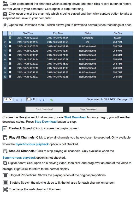
Set download locations for recordings and snapshots taken using Web Client, and choose file type
for video files.
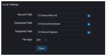
recordings to be saved on your computer.
Download Path: Click to browse for and select the folder where you would like to save the
download video recordings to your computer.
Snapshot Path: Click to browse for and select the folder where you would like the manual
capture snapshots to be saved on your computer.
File Type: Choose your preferred file type for manual recordings.
Save: Click to save the modifications.
PC/Mac
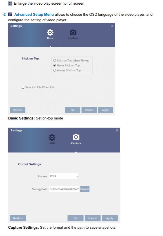
This section will help you to play the backup files with the powerful video player which is attached
in the CD.
For Mac users, please install the app “VideoPlayer_x.x.xx_xxxx_xx_x.dmg”, for example:
VideoPlayer_1.0.15_2017_01_6.dmg.
For PC users, please install the software “VideoPlayer_x.x.xx_xxxx_xx_xx.exe”, for example:
VideoPlayer_1.0.15_2017_01_06.exe.
Minimum System Requirements
• Intel Pentium 4 or above
• Microsoft Windows XP / Vista / 7 / 8 / 10
• 256MB RAM
• 16MB video memory
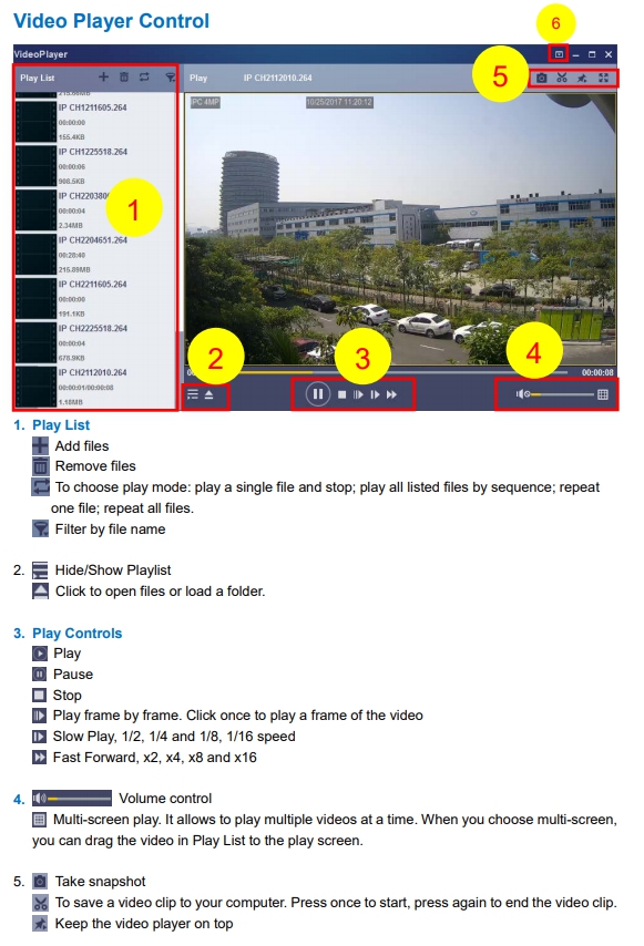
1. Install the Video Player software in the CD and run.
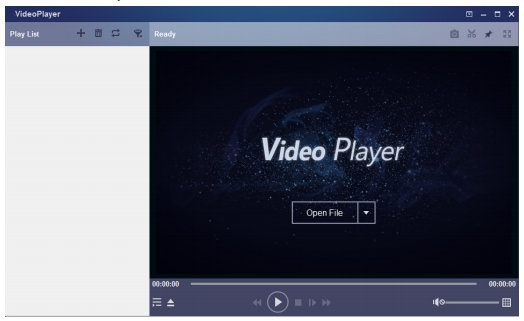
3. Click Open File button or click + button on the Play List to load single or multiple video files. It
supports to add & play “.rf”, “.avi”, “.mp4”, “.264” and “.265” files. Click button to load a
folder with backed-up videos.
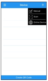
Devices
The DVR supports to remote access via mobile devices based on Android & iOS operating
system.
1) Search RXCamView from Google Play Store for android devices or App Store or iOS devices
and install.
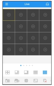
2) Run the app, it will display the live view screen.
10.1 Troubleshooting
A: Check if the power supply system is properly connected and data cord and power cables
are securely connected, and if something wrong with the HDD interface. Or you may check if
your HDD is supported by referring to the specifications or descriptions.
2. Q: I have changed the password but forget the new password, how can I access the system?
A: If you forget system password, please consult with our technical personnel. We strongly
suggest user to set password easy to be remembered and relatively safe. If you have safety
requirement, please do not set very simply password, such as 000000.
3. Q: We see abnormal video signal or even no video signal by connecting the DVR and camera
together. Power supply for both devices is OK. What is wrong?
A: Check network cable at DVR side to see if the cable is firmly connected and if it is worn out
and needs to be replaced, or to check if NTSC or PAL is selected consistently.
4. Q: How to prevent DVR from being influenced by heat?
A: The DVR needs to dissipate heat while it is running. Please place the DVR in a place with
good air circulation and away from heat sources to ensure stability and life of the DVR.
5. Q: The remote controller of DVR doesn’t work while the monitor screen is OK and panel keys
are functional. Why?
A: Operate again by aiming the remote controller at the IR receiver on front panel. If it still
doesn’t work, please check if the batteries in the remote controller are dying. If not, check if
the remote controller is broken.
6. Q: I want to take out HDD from my PC and install it in DVR. Can it work?
A: All HDDs supported by the system can be used. But remember, once DVR runs, the data
on your HDD will be lost.
7. Q: Can I playback while recording?
A: Yes. The system supports the function of playing while recording.
8. Q: Can I clear some records on HDD of DVR?
A: In consideration of the file security, you may not clear part of records. If you want to remove
all the records, you can format HDD.
9. Q: Why can’t I log in DVR client?
A: Please check if the network connection settings are correct and RJ-45 port is with good
contact. And check if your account and password are correctly input.
10. Q: Why can’t I find any records during playback?
A: Please check if the data line connection for HDD is OK and system time is properly
adjusted. Try a few times and restart. If it still doesn’t work, check if the HDD is broken.
11. Q: Why DVR cannot control PTZ?
A: Please check if:
a) PTZ in the front side is malfunctioned.
b) Setting, connection and installation of PTZ decoder are not correct.
c) PTZ setting of DVR is not correct.
e) Address of PTZ decoder does not match that of DVR.
f) If many decoders are connected, the farthest side of AB line of PTZ decoder should be
added 120Ω resistance to realize reflection suppression and impedance matching.
Otherwise, PTZ control will be unstable.
12. Q: Why doesn’t dynamic detection work?
A: Please check if the motion detection time and motion detection regional setting are correct
and if the sensitivity is set too low.
13. Q: Why doesn’t alarm work?
A: Please check if the alarm setting, alarm connection and alarm input signals are correct.
14. Q: Why does buzzer keep alarming?
A: Please check the alarm setting, check if motion detection function is enabled and object
motion is detected all the time and if I/O alarm is set as Always Off. Besides, refer to
corresponding HDD alarm setting.
15. Q: Why can’t I stop recording by pressing “STOP” button or click “Stop Recording” in context
menu?
A: Pressing Stop or Stop Recording can only stop manual record. If you want to stop
Scheduled recording in certain time quantum, please change the setting to No Record. To
stop Startup recording, please change record mode to scheduled recording or manual
recording. Then you may stop recording by the prescribed methods. And another way of
stopping recording is to set channel as off status in record setting.
10.2 Usage Maintenance
1. To shut down DVR, please firstly shut down the system and then turn off the power. Do not
turn off the power directly or HDD data will be lost or damaged.
2. Please keep DVR away from heat sources or places.
3. Clean the internal dust regularly. Make sure the good ventilation of DVR so as to ensure the
good heat dissipation.
4. Please do not hot plugging audio and video cables, or cables connected to ports like RS-232
or RS-485. Otherwise the ports will be damaged.
5. Please check the HDD cable and data cable regularly to see if they are ageing.
6. Please prevent the audio and video signals of DVR from being intervened by other electronic
devices, and prevent the HDD from being damaged by static electricity and induced voltage.
If the network cable is frequently plugged, it is suggested to replace connecting line regularly,
or the input signal may be unstable.
7. This is a class A product. It maybe bring wireless interference in life. Under this situation, it
need user to make measures.
เนื้อหาที่เกี่ยวข้อง

คู่มือการใช้งาน เครื่องบันทึกภาพ NVR 8000 serie
24 ก.ค. 2562

คู่มือการใช้งาน เครื่องบันทึกภาพ NVR WIFI KIT 3
24 ก.ค. 2562

คู่มือการใช้งาน เครื่องบันทึกภาพ Hiview
24 ก.ค. 2562

คู่มือการใช้งาน เครื่องบันทึกภาพ NVR 9700 serie
24 ก.ค. 2562